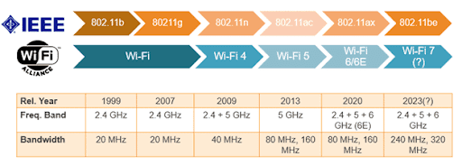
Wi-Fi 6 (802.11ax) is becoming the focus point of wireless networks everywhere as we slowly start to upgrade our existing hardware and software to utilise the added features for ours and users benefits. This blog post is an overview of the features that have been brought in with Wi-Fi 6 to reacquaint myself before I get too stuck into Christmas.
Wi-Fi 6 MU-MIMO
The previous two iterations of the wireless standard have allowed for the use of more than one concurrent transmission from a single transmitter known as a spatial stream. This is most notably with 11n the first standard that allowed four max and brought in the use of (Multiple Input Multiple Out) to utilise this increase in transmit potential. This in theory allowed up to four signals to be sent at the same time from the same device, four times as many bits, increasing overall throughput.
8011.ac ramped that number up to eight max spatial streams that allowed eight times the bits (simple maths isn't it) and the addition of multiple user (MU-MIMO) which was a shortfall of MIMO only allowing one user at a time under utilising the medium. This was however limited to downstream from the AP to the client due to the limitations of client devices and their hardware capabilities. You also tended to not find many APs using 11ac that had the capabilities of eight spatial streams again due to limitations (specifically chipsets) but that is starting to change with Wi-Fi 6.
With Wi-Fi 6 (11ax) you are seeing the next generation of Access Points being released by multiple vendors with eight spatial streams specifically most notably for the 5Ghz radio, Cisco 9130 and Aruba 550 being a prime example of the new generation of APs. This in turn will allow for larger quantities of traffic and will improve overall capacity of the medium.
Building upon the earlier use of MU-MIMO, the standard now allows for MU-MIMO downstream and now upstream from the client to the AP due to improved hardware within personal devices. Even though this does result in a slight decrease in speed overall for a single device, it does cut down on congestion of the medium by allowing many more devices to transmit simultaneously. This greatly benefits high bandwidth applications such as video that are constantly needing to transmit large packets to stop any determent to the service.
The image below is a perfect example of the differences between MU-MIMO without and with the upstream capabilities on a client device.
https://ytd2525.wordpress.com/2020/06/13/su-mimo-vs-mu-mimo-difference-between-su-mimo-and-mu-mimo/
OFDMA
Most recent standards use Orthogonal Frequency-Division Multiplexing (OFDM) which is an an efficient form of modulation format and is built upon in Wi-Fi 6 with
Orthogonal Frequency Division Multiple Access (OFDMA). They both uses the functionality of Frequency Division Multiplexing (FDM) and Quadrature Amplitude Modulation (QAM) with some slight changes.
Frequency Division Multiplexing (FDM) is a technique that is used to split up the available bandwidth into sections of subcarriers (or tones) within a channel. All of the subcarriers will overlap but not to the point where the peaks are not distinguishable by the receiving device. This allows multiple sections within the bandwidth itself to be used to pass bits organised into what is called symbols therefore increasing the data rate.
OFDM used in 11a/g/n/ac on a 20Mhz channel is split into 64 sub carriers. Each is separated by 312.5kHz away from the adjacent subcarriers and their centre frequency (312.5 x 64 is 20,000, i.e. 20Mhz size of the channel). The transmission of one of these symbols is 3.2 microseconds, and then we wait for what is known as a guard interval. There is two types of guard interval, long 0.8 microseconds and short 0.4 microseconds to stop any reflections from effecting the main signal. Shorter guard interval means you wait less before transmitting the next, improving the data rate, but you do wait less to offset any potential interference.
With OFDMA the space between the channels is 78.125kHz, which if you have a calculator handy, divide 20,000 by that number (again 20Mhz channel) and it gives you 256 overall subcarriers available. Symbol transmission duration is extended to be 12.8 microseconds and with guard intervals of either 0.8, 1.6 or 3.2, an additional increase as well. Having subcarriers being so close there had to be additional measure in place to limit interference. You would assume that having an increased duration and guard interval would hinder speeds and actually lower speed, but with the increased quantity of subcarriers and better resistance to interference you will see an increase in throughput overall and is hugely beneficial when it comes to noisy environments. The image below shows the overlapping subcarriers and the peaks which are unaffected by neighbouring carriers.
https://www.researchgate.net/figure/Multi-carriers-of-OFDM-signal-20_fig2_321278034
Another addition to the subcarriers within OFDMA is that the subcarriers can be distributed and sectioned separately among different devices. One of the issues with OFDM is a single device transmission over a subcarrier. A device may not require the entire capacity of said carrier, overall forcing some of the subcarriers to be under utilised by smaller transmissions.
OFDMA greatly improves upon this by allowing subcarriers to be grouped in what is called Resource Units (RUs) of various sizes such as 26, 52, 106, 242 and even higher if you have channel bonding configured. The AP gathers devices into groups that will not interfere or hinder the others and subsequently allocates each device within each group a transmit opportunity within the different subcarriers. Overall this better utilises the medium especially for smaller packet applications that do not require as much transmit time as others but still require access.
The below image shows OFDM allowing the same device to utilise their specific subcarrier through the transmission duration, while OFDMA is sectioning the particular subcarriers up to different devices as required.
https://blogs.arubanetworks.com/solutions/whats-the-difference-between-ofdma-and-mu-mimo-in-11ax/
QAM is another part of OFDM/OFDMA and is a modulation technique that utilises a phase and amplitude component allowing it to better represent bits over the medium then others (Amplitude for example). Depending on the tip of the peak of each wave, depends on the specific bit sequence that it represents. Take the image below as an example of 16-QAM (16 options) and 64-QAM (64 options).
https://www.gaussianwaves.com/2012/10/qam-modulation-simulation-matlab-python/
When you use a wider option of sequences, they increase in length as more choice introduces greater levels of available complexity. This allows each wave to send and receive more bits overall, increasing throughput. This does require a less noisy Radio Frequency (RF) and a higher Signal to Noise (SNR) as any interference may result in errors.
To try and alleviate any issues when it comes to errors, a percentage of the signal is re-transmitted. This is represented by a fraction a shows the amount of new bits being transmitted each time. For example if 25% is re-transmitted for error checking, the coding will represented as 3/4 due to 75% of the new information being new and 25% being bits from the previous symbol.
Wi-Fi 6 went one step further and now allows 1024-QAM. With this level of complexity the increase in throughput is increased for any device capable of using it. But to comfortably use the more complex modulations remember that you need higher levels of SNR and may not be obtainable in some environments. You can find the additional data rates (and the coding) for Wi-Fi 6 on the following link: https://bit.ly/2G0DIcD
Target Wake Time (TWT) and BSS Colouring
To combat the issues regarding battery usage on small portable devices such as laptops and mobiles Target Wake Time was introduced. With this solution a device or the AP may tell each other how many times the device will wake. This device may then stop utilising its wireless network adapter stopping any power consumption without sending or receiving anything and more importantly without losing association to the AP.
The AP as a result will keep all received traffic in a type of buffer and without asking the device if its awake sends the information on the given schedule, so to save time it does not wait. This is super important for personal devices when it comes to battery usage but is also beneficial for IoT devices that do not transmit as frequently saving power. I have heard that the longest sleep period available is 5 years, which is crazy.
BSS Colouring was introduced to combat issues with high density deployments and the impact of Co-Channel interference (CCI). This allows BSS to be differentiated through the use of "colouring" which is actually a numerical identified of the BSS. Like naming two David's, Dave1 and Dave2. The device associated to the AP, if encountering CCI from a neighbouring AP on the same channel will simply ignore it. This greatly benefits high density deployments and hopefully brings a bit of life back in 2.4Ghz.
https://forum.openwrt.org/t/802-11ax-bss-coloring/36597


Comments
Post a Comment