5Ghz Features and Data Rates
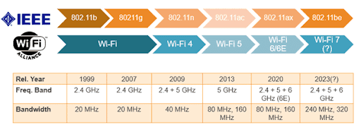
The usage of 5Ghz frequency and the inevitable progression of the wireless standard has led to many benefits over the years. The most notable advances being the latest three standards; 802.11n known as the High-Throughput, leading to 802.11ac known as the Very-High-Throughput and 802.11ax (Wi-Fi 6) known as High-Efficiency.
With these new standards a huge list of benefits comes not only to personal usage at home but also corporate space. Most notably one of the main benefits is data rates (as per the first two standard’s names).
802.11n (High-Throughput) built upon previous released standards, 802.11a for 5Ghz and 802.11g for 2.4GHz which achieved throughputs around 50Mbps. 11n bumped the data rate up all the way to a max 600Mbps which is a huge increase giving rise to its name. From here, any future standards such as 802.11ac or 11ax have always added to the ever-growing max data rates available, 11ac being nearly 7Gbps and 11ax on the push for the 10Gbps barrier. But with the increase in data rates, what has changed?
One of the features that allowed data rate increase was the maximum channel width increase, known as Channel Bonding. It allows an Access Point (AP) or home router to take up additional adjacent channels. This was first introduced in 11n with a maximum cap of 40Mhz channels instead of 20Mhz and eventually 11ac introduced 80Mhz and then 160Mhz channels. The diagram below provides a bit of context to Channel Bonding with the channels listed at the top from 36 – 64 and the effects of 20Mhz, 40Mhz, 80Mhz and 160Mhz on said channels.
As you can see, the higher channel width, the more space you have available. A perfect example of visualising this in a real-world example is a motor way. As the number of lanes increase so does its capacity for cars, the same way having additional channels increases your overall ability to pass traffic. One of the main issues with Channel Bonding is that you lessen the overall available channels (earlier blog post I mentioned ACI and CCI) that can be split between the APs in a corporate environment or between you and your neighbours without interfering. Think of it as there only being a finite number of lanes available, if you keep trying to use the most possible you may start to have issues eventually.
Another of the benefits is the devices use of Multiple In – Multiple Out (MIMO). You may see for example while browsing wireless devices a mention of 3x3 or 4x4 among other variations and most likely an additional number after a colon for example 3x3:3. These sets of numbers are described as shown below:
There are three transmit antennas, which is noted by the first digit (3x3:3), the second digit represents the number of receive antennas (3x3:3) with the final number after the colon (3x3:3) showing possible spatial streams.
Transmit Antennas x Receive Antennas : Spatial Streams
All three of the above are vital in providing MIMO features. First the ability to send and receive on additional antennas, enhances the signal that you will receive and send. An example of this is sending three post cards all saying the same thing. If you only sent one and made an error or it has been damaged in transit the message may be difficult to understand by the recipient. While sending three or four of the same messages to multiple receivers allows the device to notice any potential faults when comparing the messages. Think of it more as a reassurance of the intended message and with reassurances comes less need for re-transmissions and subsequently more time to send the next set of data resulting in higher data rates. Example below showing 4 Transmits and 4 Receive antennas.
In addition to this you have Spatial Streams that splits the data into separate parts. For example, three spatial streams correspond to three different sections of the message. If you compare between a one and two spatial streams, the throughput is hypothetically doubled.
Remember that spatial streams also rely on the number of antennas, you will never find a 3x3:5 as you are missing two additional antennas required to create five streams of traffic. 11n allowed up to 4x4:4 and 11ac allowed up to eight spatial streams but you never see greater than four primarily due to hardware limitations. You will be hard pushed to find many home devices that currently support any higher than four.
One of the less noticed features which allowed for another small increase in data rates is Guard Interval (GI). This was introduced in 11n going from 0.8 μs to 0.4 μs and built upon in 11ax by allowing higher intervals which we will discuss later. A GI is a period of time taken after sending data to allow for the data to travel, thus potentially limiting the effect the environment may have when the signal travels to the destination (such as multipath). Reducing the GI allows you to have less idle time between sending but may cause an increase in errors at the other end. Think of it like shouting down a tunnel, if you do not wait to shouting again you start to garble up the first message which is a pain for whoever is at the other end listening to you. In 11ax this can be increased to 1.6 μs and 3.2 μs but the idea is to find a happy medium as having an increased wait time does reduce error rates but can also add un-warranted idle time.
Thank you for reading. I will later expand upon some of the other features next week such as Modulation, Coding and Signal to Noise ratio, which are some of the additional factors that come into play when deciding the data rates available.
Sources:
https://www.everythingrf.com/community/what-is-mimo-technology


Comments
Post a Comment